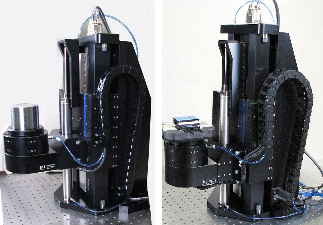
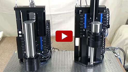
3D Computerized Tomography (CT) and micro computed-tomography (micro-CT) systems are used to study the internal structures of a wide variety of material samples. PI’s air bearing systems group has built a number of motion systems that are used in research labs around the world. The system creates ultra-precise motion as it rotates and lifts a sample in a series of helical moves. The motion involves tracing a helical path, i.e. a small angle (0-5degrees) and a tiny change in Z (0-0.1mm), moved synchronously. After each small step, the system remains stationary for several seconds while the image is acquired. Each image is a full cross-sectional view of the sample. A series of 2D image “slices” are assembled in software to create a 3D image.

The sample will sit approximately 100mm above the theta tabletop mounted on a long straight post, so any position deviation or error (such as wobble, eccentricity, pitch, and yaw) will magnify sample position error. The goal is to achieve an alignment error between each image slice of less than 50nm. The image slices can then be aligned in software with minimal distortion.
This system has been built with a pneumatic counterbalance that supports the gravity load of the Theta stage and the user payload, so that the Z axis stage motor does not need to lift the payload against gravity; it only needs to overcome the inertia. Without such a counterbalance, the Z stage motor would overheat.
The counterbalance system features an auto-calibration control algorithm. The system, when active, will automatically detect the payload applied to the Z-Theta stage and compensate accordingly. There are no manual user adjustments required to accommodate varying payload masses.
Performance Summary
- Sample payload: Up to 10 kg; limited to 1 kg if XY stage option is used
- Z Travel: 200mm
- (Optional) XY Travel: 26x26mm
- Z Position Accuracy, Repeatability: ±200nm, ±50nm
- Theta Axis Error Motion Axial, Radial, Wobble: 50nm, 100nm, 1.5µrad
Details of System Components

Major components used in the helical tomography motion system: A-812 advanced ACS motion controller, A-623 rotary air bearing stage, and A-123 linear air bearing stage
- PIglide A-123 Z Axis, linear air bearing stage with brushless linear motor drive, optical linear absolute encoder, 200mm travel, counterbalanced, with cable and pneumatics loops.
- PIglide A-623 Theta Axis, rotary air bearing with brushless torque motor drive, optical rotary absolute encoder, continuous 360° travel, mounted to Z axis. Custom slip-ring assembly, 56 channels, for XY stage signals.
- (Optional) XY Stage, Q-545-based miniature piezo motor stage, 26x26mm Travel, absolute optical encoder for closed-loop position control, BiSS-C Interface. Mounted to Theta stage via custom adapter plate
- Pneumatics panel with air filtration, pressure regulation, pressure interlock, counterbalance regulation
- PIglide A-812 Series 2-Axis Motion Controller, featuring ACS SPiiPlus Technology, PWM servo drives with power supply, 120-240 VAC input, 60 VDC motor buss, 19” rack mount enclosure, absolute BiSS-C encoder inputs, Ethernet interface
- (Optional) Single Axis Controller (2x) 1 each for the X and Y stages. Ethernet, USB, and RS-232 communications.


