ABOUT US
Our Piezomotors Operate Based On A Newly Patented Technology
Founded in 2024, Piezo Motor Company is at the forefront of innovation in the design and manufacturing of piezoelectric motors. Headquartered in the USA, we have a global reach through a network of international distributors, delivering cutting-edge technology to clients worldwide.
Our team comprises highly skilled experts with extensive experience in piezoelectric motor and actuator design and physics. We are passionate about harnessing the unique properties of piezoelectric materials to create motors that offer unmatched precision, efficiency, and reliability. Our solutions are tailored to meet the diverse needs of industries ranging from medical devices to aerospace and robotics.
We pride ourselves on our commitment to excellence and innovation, continuously pushing the boundaries of what piezoelectric technology can achieve. Our dedication to research and development ensures that we remain leaders in this dynamic field, providing our clients with the most advanced and effective solutions available. Join us on our journey as we revolutionize the world of motion control with piezoelectric technology.
Technology & Innovation
Design Basis
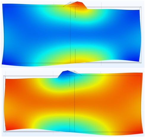
Piezo Motor Company piezomotors operate based on new patented technology. Electrical excitation of a rectangular piezoceramic body (resonator) induces simultaneously two independent longitudinal and bending ultrasonic standing waves in two perpendicular directions. This action generates elliptical vibrations at the resonator’s center, resulting in linear motion of the motor, which is passively in contact with the resonator body.
The resonator is designed to generate simultaneously a first order longitudinal mode of vibration along the width (frequency v1) and a bending mode of vibration along the length (frequency v2). Within the oscillator assembly the combination of the two orthogonal modes of vibration create elliptical movement of the resonator contact site. Motion occurs as the result of frictional force between the contact site and rotor/liner slide.
Motion Control Using the Open-Loop Driver PCB
Piezo Motor Company (PMC) motors are available with or without factory-fitted encoders, enabling both open-loop and fully closed-loop motion-control configurations.
Motion control is achieved using PMC’s compact, cost-effective electronic driver PCBs, designed specifically for use with the full range of PMC piezomotors. The primary function of the driver PCB is the generation of electrical drive pulses with defined frequency and amplitude to excite the piezomotor. Each driver PCB is factory-programmed and optimized for the specified motor model, ensuring optimal performance, stability, and integrated control functionality.
PMC driver PCBs are available in both open-loop and closed-loop configurations.
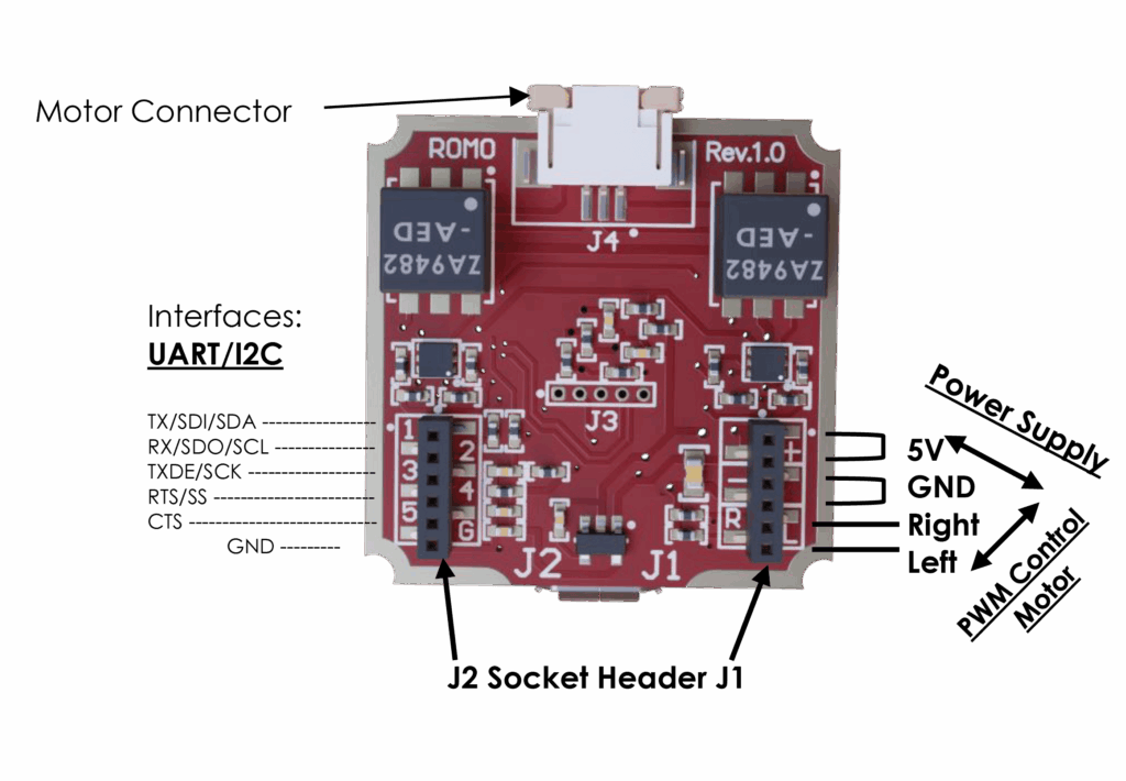
Electronic Driver Board Interfaces
Supported interfaces: PWM, UART, and I²C
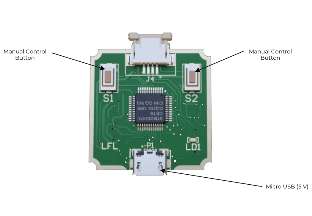
Open-Loop Driver
- UART interface – The motor can be controlled by using UART commands through the pins 1,2,3,4,5,6 (TX,RX,TXDE,RTS,CTS,GND) of J2 connector.
- SPI interface – The motor can be controlled using SPI interface through the pins 1,2,3,4,6 (SDI,SDO,SCK,SS,GND) of J2 connector.
- I2C interface – The motor can be controlled using I2C interface through the pins 1,2,6 (SDA,SCLGND) of J2 connector.
- Direction
- Start / Stop
- Operating Mode (PWM or Continuous)
- PWM Duty Cycle setting